Exoskeleton Sensors: What Each Signal Measures
A source-led guide to encoders, IMUs, pressure insoles, force sensors, motor current, EMG, cameras and the estimates built from them.

Research standard: this guide draws on primary records, technical documentation and documented field experience. Volatile facts such as price, availability and firmware are reviewed on a dated schedule.
Start with the measurement boundary
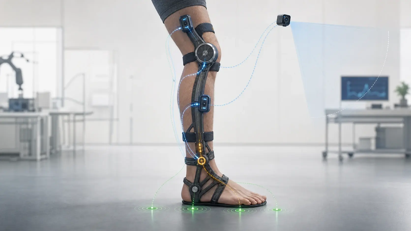
A sensor name does not tell you which physical quantity reaches the controller. A rotary encoder can report a motor-shaft angle, a gearbox-output angle or a device-joint angle. An inertial measurement unit can report acceleration and angular velocity from the segment where it is mounted. A pressure element under the foot responds to local contact. Each signal belongs to a specific location and coordinate system.
The controller may derive other values from those raw measurements. It can differentiate an angle to estimate velocity, combine accelerometer and gyroscope data to estimate orientation, segment a stride from foot-contact events or convert calibrated motor current into an estimated actuator torque. These calculations are useful, but the derived value should not be relabeled as a direct measurement.
This boundary also matters when comparing papers. Device-joint torque, force in a cable, pressure beneath one part of the foot, estimated biological joint moment and muscle electrical activity describe different parts of the human-device system. A clean comparison records what was sensed, where it was sensed, how it was processed and which output the controller used.
| Sensor or signal | Direct measurement | Common derived use | Boundary to preserve |
|---|---|---|---|
| Encoder or potentiometer | Rotation or position at its mounted shaft or joint | Angle, angular velocity, phase features | Device motion is not automatically biological-joint motion |
| IMU | Linear acceleration and angular velocity; some units also sense magnetic field | Segment orientation, motion state, gait features | Output depends on mounting, calibration and estimation method |
| FSR or pressure insole | Local pressure or force response at instrumented contact areas | Heel strike, toe-off, stance state or load distribution | Partial contact sensing is not a full force-plate measurement |
| Strain gauge, load cell or torque sensor | Deformation, force or moment at a defined structure | Feedback control and transmission-load estimates | Location determines which load path is being measured |
| Motor current | Electrical current at the actuator | Calibrated actuator-torque estimate | Friction, transmission losses and interface motion remain outside the direct signal |
| Surface EMG | Electrical activity at instrumented muscles | Movement features or comparison outcome | Placement, preparation and processing are study-specific |
| Camera | Images of the scene or wearer | Terrain, object or movement-context features | Field of view, lighting and training data constrain the inference |
This table synthesizes sensor roles documented in the six studies listed below. The sources were verified on 7 August 2026; no row defines a universal hardware set.
Encoders report device motion
In the studies on this page, encoders or potentiometers record motion at a device joint or actuator. Record the sensor type, zeroing method and location along with the label: motor shaft, transmission output, exoskeleton joint or another moving part.
A device-joint angle can be a useful proxy for body motion when the frame and wearer move together. Compliance and interface motion can break that assumption. In the 2024 M-BLUE ankle-module study, researchers mounted IMUs on the foot and shank and used the difference between their orientation signals as an ankle-angle estimate. They reported that this estimate was better for their rigid-body model than the motor encoder alone because the mechanical interface was compliant. That is a result for the documented setup, not a rule that IMUs always outperform encoders.
IMUs describe motion where they are mounted
In the studies on this page, IMUs supply acceleration and angular-velocity channels at their sensor housings. Orientation, segment angle and gait-state variables require calibration, coordinate transforms, filtering or a model. Mounting an IMU on a trunk, thigh, shank or foot therefore produces different information even when the hardware is identical.
The 2025 npj Robotics knee-exoskeleton study provides a concrete sensor map. Potentiometers supplied right and left knee angles and angular velocities, while a trunk-mounted IMU supplied sagittal and coronal motion variables. An eyeglass-mounted RGB camera added a first-person scene image. The model combined those inputs to predict active or free commands. The experiment involved two participants, so it demonstrates one multimodal architecture rather than a general sensor requirement.
A second study used a different combination for a different question. The 2024 Frontiers hip-exoskeleton experiment included absolute joint-angle encoders, motor-current sensors, a lower-back IMU and instrumented insoles. One controller used foot-loading information, while another used hip-phase information. Both were implemented on the same device, which makes the paper useful for showing that available sensors and selected controller inputs are separate design choices.
Foot sensors can mark contact without reproducing a force plate
Foot switches, force-sensitive resistors and pressure insoles are often used to identify heel contact, toe-off or the transition between stance and swing. Several sensing cells can also show how load moves across instrumented parts of the foot. Coverage and calibration define what those signals can support.
The Frontiers hip study used eight-cell insole FSRs to estimate foot-contact information. For its ground-reaction-force-difference controller, the authors explicitly stated that precise force measurement was unnecessary and that the sensors did not cover every contact point for every foot. The normalized left-right signal was adequate for that controller input. It should not be presented as a complete calibrated ground-reaction-force record.
The 2022 Nature ankle-exoskeleton study used pressure sensors at four foot locations to detect heel strike and segment gait cycles. The same system also carried a rotary ankle encoder and strain gauges on the heel spur. That combination separated contact timing, device motion and measured torque instead of asking one signal to represent all three.
Load sensing depends on where the load crosses the sensor
A load cell, strain-gauge bridge or rotary torque sensor measures force or moment through a defined structure. If the sensor sits in a cable path, it describes cable tension. If it sits at a device joint, it describes the moment across that joint. If it appears only in a benchtop fixture, it characterizes actuator output under the test configuration. None of these placements directly measures every force transferred through cuffs, straps and tissue.
The Nature ankle device placed strain gauges in a full Wheatstone bridge on the heel spur to measure exoskeleton torque. Its sensor records were sampled at 2,000 Hz, while the portable control and optimization loop ran at 200 Hz. Those rates belong to different layers of the same system. Reporting only the larger number would obscure which process it describes.
The Frontiers hip device took another route. It had no direct force or torque sensor, so the researchers estimated applied torque from motor current using a relationship identified in benchtop calibration. The paper keeps the limitation visible. Motor current was a practical feedback signal for that device, not proof that the same current-to-torque relationship applies across transmissions, temperatures or body interfaces.
EMG and cameras measure different context
Surface electromyography records electrical activity from muscles beneath prepared skin electrodes. It can contribute to intent-estimation research or serve as an outcome measure, depending on the protocol. Those roles must stay separate. An EMG channel used to evaluate a controller is not automatically an input to that controller.
In the npj Robotics study, six muscle channels around the right and left knees were collected for EMG-based comparison methods and for evaluating the movement trials. The proposed vision-and-kinematics controller instead used knee motion, trunk motion and RGB images. The source therefore documents both sensor families without claiming they were interchangeable or used for the same step.
Cameras add environmental information that joint sensors cannot see directly. They can supply image features about a step, object or route ahead. They also introduce a different failure surface: field of view, occlusion, lighting and the diversity of training scenes. The 2025 study reported weaker recognition for some previously unseen step colors and shapes before fine-tuning, which keeps its demonstrated scope narrower than a general claim of environmental understanding.
Sensor fusion is a model, not a magic sensor
Combining signals can resolve ambiguities. An encoder can show that a joint moved, an insole can show that the foot is loaded and a strain gauge can show the moment transmitted through a device structure. The controller still needs a defined method for aligning timestamps, filtering noise, handling missing data and turning those channels into a state estimate.
The 2024 Nature task-agnostic-control study tested this dependence directly through sensor ablations and simulated sensor dropouts. Its extended-data analysis compared performance after removing combinations or individual inputs across 28 tasks and 10 participants. The analysis shows why an estimator should be evaluated with the actual inputs it expects and with explicit missing-signal tests, rather than treating one published sensor suite as universally best.
Label training measurements separately. Motion-capture cameras, force plates and laboratory EMG can provide ground-truth data for developing or validating a model even when they are absent from the portable device. The 2023 Scientific Data release collected motion capture, IMUs, force plates and EMG from 12 participants across 20 non-cyclic and 11 cyclic activities. That dataset describes a research measurement environment, not a bill of materials for a finished exoskeleton.
| Study | On-device or wearable signals | What the setup demonstrates | Limit to retain |
|---|---|---|---|
| Baud et al., Frontiers (2024) | Joint encoders, motor current, lower-back IMU, eight-cell insole FSRs | One device can support controllers built around different input signals | No direct torque sensor; current-to-torque relationship came from calibration |
| Slade et al., Nature (2022) | Ankle encoder, four-point pressure insole, heel-spur strain gauges | Contact, kinematics and device torque can be measured at separate boundaries | Sensor rates and optimization results belong to the tested ankle system |
| Zhao et al., IEEE BioRob (2024) | Foot and shank IMUs plus pressure insole during the human test | Segment sensors can estimate ankle angle across a compliant interface | Human validation was a single-participant case study |
| Furukawa and Morimoto, npj Robotics (2025) | Knee potentiometers, trunk IMU and eyeglass RGB camera | Visual and kinematic history can feed an active-or-free command model | Two participants and a bounded squat, walk and step-up sequence |
| Molinaro et al., Nature (2024) | Multi-sensor exoskeleton data evaluated through ablation and dropout | Sensor contribution can be tested rather than assumed | The reported analysis used its trained estimator, tasks and participant set |
This comparison covers the documented sensor inputs and validation scope of five primary studies, all rechecked on 7 August 2026. It does not compare product quality or whole-system performance.
A practical sensor-reporting checklist
- Name the raw physical quantity, sensor type and mounting location.
- Separate measured values from filtered, differentiated, calibrated or model-estimated values.
- Record coordinate frames, zeroing procedure, sampling rate and controller update rate where the source provides them.
- Identify which sensors feed the controller and which are present only for evaluation or ground truth.
- Keep motor current, actuator output, transmission load, device-joint torque, interface force and biological-joint moment in separate fields.
- Report the movements, participants, environment and missing-signal tests used to validate an estimator.
Sources
- Frontiers: comparison of two hip-exoskeleton controllers (2024)
- Nature: portable rigid-frame ankle exoskeleton (2022)
- IEEE BioRob: modular backdrivable ankle exoskeleton (2024)
- npj Robotics: vision-and-kinematics knee-assistance control (2025)
- Nature: biological hip-and-knee moment estimation (2024)
- Scientific Data: lower-limb biomechanics and wearable-sensor dataset (2023)
Key facts
- An encoder usually reports motion at a device shaft or joint, not the biological joint directly.
- An IMU measures acceleration and angular velocity; orientation and body-segment motion are derived through processing.
- Pressure and force-sensitive insoles can identify contact timing even when the setup is not designed to measure a complete ground-reaction-force record.
- Motor current can support a torque estimate after calibration, but it is not a direct interface-force measurement.
- EMG and cameras add biological or environmental context, while introducing placement, calibration or visibility constraints.
- Sensor placement, synchronization and the stated baseline matter as much as the sensor category name.
Frequently asked questions
What sensors are used in exoskeletons?
Research exoskeletons may use encoders, potentiometers, IMUs, pressure or force-sensitive insoles, strain gauges, load cells, torque sensors, motor-current sensing, EMG or cameras. The exact combination depends on the mechanism and controller. A category list is incomplete unless it also states where each sensor is mounted and what the system derives from it.
Can an encoder measure the wearer's joint angle?
An encoder measures rotation where it is mounted, often at a motor shaft or device joint. That value can approximate body-joint motion when the device and wearer move together, but compliance, attachment motion and axis differences can separate them. A study should state whether body angle was measured independently or inferred from device motion.
Do pressure insoles measure ground-reaction force?
Some calibrated pressure systems can estimate components of foot loading, but coverage and calibration matter. A few FSR cells used to detect contact do not reproduce a laboratory force plate. Report whether the source measures local pressure, detects an event, estimates vertical force or reconstructs a broader force quantity.
Is motor current the same as exoskeleton torque?
No. Current can support an actuator-torque estimate when the motor constant, gearing and calibration are known. Friction, transmission behavior, structural deformation and body-interface motion can separate that estimate from device-joint torque or the moment transferred to the wearer.
Why combine several exoskeleton sensors?
Different sensors resolve different parts of the state. Joint motion alone may not show whether the foot is loaded, while foot contact alone does not describe joint velocity or transmitted torque. Fusion can reduce ambiguity, but it requires synchronized signals, a documented model and tests for missing or degraded inputs.