Exoskeleton Materials: A Component-by-Component Guide
A research-led map of structural composites, metals, polymers, textiles, padding and fasteners across wearable-robot components.

Research standard: this guide draws on primary records, technical documentation and documented field experience. Volatile facts such as price, availability and firmware are reviewed on a dated schedule.
The material name is only the first field
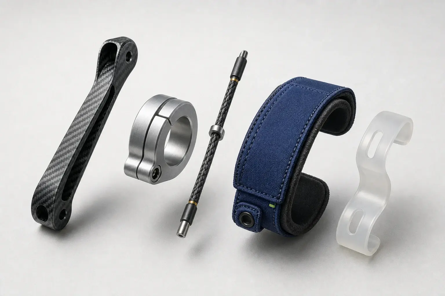
A useful materials comparison starts below the product label. Carbon fiber may form a long link, a thin plate or a shaped shell. Aluminum may be a joint housing, a connector or an actuator fitting. Textile may mean stretch knit, low-stretch webbing, mesh, hook-and-loop tape or a padded cuff. Those parts face different forces and are manufactured in different ways, so grouping a whole device under one material hides the engineering decision that matters.
This page owns that component-level question. The exoskeleton-types guide classifies systems by power source, body region, structure and intended use. The exoskeleton-versus-exosuit guide follows the primary load path and naming boundary. Here, the task is narrower: identify what each material does, where it sits and which evidence would support a comparison. No material creates an automatic product category or verdict.
| Component role | Material examples in current research | Evidence to look for |
|---|---|---|
| Structural link or plate | Carbon-fiber composite, aluminum | Layup or alloy, cross-section, span, load direction and measured deflection |
| Joint, connector or fastener | Machined aluminum, steel hardware, bearings | Geometry, interface method, range of motion and assembled test condition |
| Cable or tendon path | Braided rope, coated cable, polymer tube | Routing, tension measurement, friction, travel and attachment points |
| Garment and anchor | Stretch knit, mesh, non-stretch fabric, webbing | Zone, direction of stretch, recovery, anchor migration and test load |
| Padding or shaped mount | Foam, elastomer, printed polymer | Thickness, contour, compression and interface measurement |
| Actuator element | Motor metals, silicone bladder, polyester braid, shape-memory alloy | Actuator architecture, operating condition and separate output measurement |
The table is a reporting map, not a recommendation matrix. A material can appear in more than one row, and the same component can combine several materials. ASTM F3323-24 supplies a common terminology scope for exoskeletons and exosuits across research, design, deployment and use. That shared language helps describe a device, but it does not reduce architecture to a carbon, metal or textile label.
Carbon fiber is a designed structure, not a magic adjective
Carbon fiber is usually encountered as a composite: reinforcing fibers sit inside a matrix and are arranged into a laminate, tube or molded part. The finished member depends on fiber direction, layer sequence, wall thickness, cross-section, joints and manufacturing quality. Two parts described as carbon fiber can therefore have different stiffness, mass and behavior. A material name without those construction fields is not enough for a technical comparison.
A 2022 Nature ankle-exoskeleton study offers a concrete component map. Its portable prototype combined carbon-fiber and aluminum framing with a motor, drum and rope transmission, then connected to the wearer through a shoe and calf strap. The paper states that the carbon-fiber frame used both a stiff material and a cross-section with a high area moment of inertia to limit meaningful deflection under the prototype's loading. Material and geometry were part of the same decision.
That example does not prove that carbon fiber is always lighter, stiffer or better than a metal alternative. The paper describes one frame designed around a defined torque range, shape and test protocol. A fair record would capture whether a published mass covers the bare composite, bonded inserts, hardware and protective layers; how the part is loaded; and whether stiffness was simulated, bench-tested or measured only within the assembled device.
Why metals remain in composite frames
Wearable structures need more than long links. They also need holes, threads, bearing seats, clamping surfaces, pivots and interfaces to motors or transmissions. Those localized features can be made from a different material than the main strut. The useful question is not carbon fiber versus aluminum for the entire exoskeleton. It is which component uses each material and how the joint between them is constructed.
A 2024 npj Flexible Electronics prototype makes that mixed construction visible. Its adjustable upper-limb frame used carbon-fiber tubing and plates, machined aluminum connectors and stainless-steel fasteners. Thermoformed 3D-printed arm mounts connected the rigid structure to curved body geometry. The paper reported 670 grams for the frame, but the important materials lesson is the division of labor: composite for extended members, metal at connectors and fasteners, and formed polymer at the wearable mount.
Even an exploded material list would still be incomplete without assembly details. Bonded inserts, bolts, clamps and bearings create transitions between parts. Their placement changes the effective span of a member and the way loads enter it. When two research devices use the same headline materials, compare the complete structural path rather than assuming equivalent behavior from a shared ingredient list.
Printed polymers can be rigid in one direction and flexible in another
Polymer does not automatically mean soft, and 3D-printed does not identify a mechanical property. Resin or powder choice, wall thickness, infill, orientation and geometry all influence the finished part. Wearable-robot papers use printed polymers for shaped mounts, spacers, shells, guides and hybrid anchors because those roles may benefit from complex geometry or controlled compliance.
A 2025 Scientific Reports study created a chain-linking anchor as one SLS-printed nylon structure. Slender linked rods were arranged to provide high stiffness in the shear direction used for force transmission while allowing low bending stiffness around the body. In controlled dummy tests, the authors compared conventional soft, chain-linking and single-piece rigid anchors while keeping the nylon strap and buckle attachment method constant. Geometry changed while part of the material system stayed fixed.
A different 2023 Scientific Reports suit used 3D-printed thermoplastic-polyurethane supports inside its waist belt. Those pieces worked alongside fabrics, dials, buckles and routing lines rather than replacing the textile structure. Together, the studies show two polymer roles: a directionally structured anchor and a localized flexible support. They do not establish one preferred polymer or manufacturing method outside the tested prototypes.
Textile systems are zoned material assemblies
Calling an exosuit fabric-based is as broad as calling a rigid frame metal-based. A garment can use stretch material to follow body dimensions, low-stretch webbing to carry tension, mesh in a ventilation zone, elastic bands for adjustment and padded layers at interfaces. Stitch patterns, seams, edge binding, buckles and hook-and-loop fasteners are also part of the assembly because they connect and redirect those zones.
The 2023 suit-type study documented that zoning directly. Stretchy fabric covered adaptable areas, wicking fabric appeared at the side and back of the pants, non-stretch material reinforced the waist, and band material was introduced in a second design. The platform also used webbing, elastic bands, buckles, slides and hook-and-loop fasteners. Its shape-memory-alloy actuator followed a separate path through Teflon tubes, showing that garment, routing and actuator materials should not be collapsed into one soft label.
During that prototype's development, actuation deformed the garment and produced slippage, after which the researchers changed band stiffness and support geometry. That observation is more useful than a generic claim that one textile is strong. It links a material choice to a location, loading direction and observed failure mode within one design iteration. Comparable evidence should report the fabric zone, construction, preload, force path and what movement or displacement was measured.
Anchor geometry can outweigh the fabric label
Material properties do not act independently of the body and cable path. A fabric anchor may stretch, rotate or move over underlying tissue while a cable changes direction between attachment points. The measured system stiffness therefore includes the garment, connectors, body interface and test geometry. Quoting the tensile property of a fabric roll cannot substitute for measuring the assembled human-suit path.
A 2022 PLOS ONE study tested three waist-anchor positions and three thigh-anchor positions, producing nine conditions for eight participants. As the distance between waist and thigh anchors increased, measured force capability increased while human-suit stiffness decreased. The authors linked the trends to cable stroke, body curvature and interference along the force path. The result was specific to that exosuit and posture, but it demonstrates why anchor placement belongs beside material in any comparison.
This also explains why soft and rigid cannot serve as outcome labels. A rigid part can contain compliant geometry; a soft assembly can gain directional stiffness from webbing or structured inserts. A closer anchor position can change the coupled stiffness without changing the fabric. Record the material, but keep geometry, pretension, routing and measurement boundary in adjacent fields.
Padding and interfaces are structural evidence too
Padding is sometimes omitted from material summaries because it is not the main frame. Yet it sits between that frame and the body, where it can compress, spread contact and allow relative movement. A cuff description should separate its load-carrying shell or webbing from the foam, lining, closure and shaped spacer. Otherwise the reader cannot reconstruct how a force leaves the structure and enters the wearable interface.
The same boundary applies to shoes, insoles, gloves, harnesses and backpacks when they close a device's force path. In the 2022 ankle prototype, the shoe and calf strap transferred forces to the body while the carbon-fiber and aluminum frame carried structural forces. Listing only the frame materials would miss the two components that completed the interaction. Evidence should name every contact point and describe which layer carries tension, compression or positioning.
Actuator materials answer a different question
A material can also be the active element rather than the frame. The 2023 suit routed nitinol shape-memory-alloy wires as actuators, while the garment and webbing carried their reaction forces. The 2024 upper-limb study built a pneumatic artificial muscle from a silicone bladder inside polyester mesh with aluminum end fittings and stainless-steel clamps. Neither system can be described accurately by naming only its visible outer structure.
Actuator material does not replace the powered-system evidence chain. Control signal, transmission, measured output, attachment and operating condition still determine what the assembled device does. Use the materials list to understand construction; use the powered-exoskeleton guide to follow sensing, control and actuation. Keeping those intents separate prevents a material property from being mistaken for whole-system performance.
How to read an exoskeleton materials claim
- Name the exact component, not just the whole device: strut, shell, joint, fastener, cable, cuff, padding or actuator.
- Record the material form: laminate, tube, machined part, printed structure, woven webbing, knit, foam or elastomer.
- Add geometry and load direction, including cross-section, span, fiber orientation, anchor spacing or textile stretch direction.
- State the assembly method: bonded insert, bolt, bearing, stitch, buckle, clamp, hook-and-loop closure or molded interface.
- Separate a coupon property from a component test and an assembled human-device measurement.
- Preserve the tested prototype, configuration, participant count, posture or movement and comparison condition.
- Treat mass, stiffness and force transfer as separate fields rather than one material leaderboard.
- Mark unknown construction details as not verified instead of inferring them from appearance or marketing language.
What materials cannot tell you
A material list cannot establish fit, assistance, durability, service life or suitability on its own. It also cannot reveal where system mass is carried, how a controller times output, how a joint follows the body or whether an anchor moves under load. Those answers require an assembled design and an explicit test boundary. Even a detailed bill of materials is evidence of construction, not a verdict.
For research comparisons, the strongest format is a component map paired with measured behavior. Show the frame, transmission, actuator, interfaces and fasteners separately; then state which property was tested at each level. That approach allows carbon fiber, aluminum, printed polymers and textiles to be compared in context without turning any one material into a shorthand for quality.
Sources
- ASTM F3323-24: Standard Terminology for Exoskeletons and Exosuits
- Nature: portable rigid-frame ankle exoskeleton (2022)
- Scientific Reports: anisotropic anchoring for a soft wearable robot (2025)
- Scientific Reports: garment-routed soft wearable robot (2023)
- PLOS ONE: hip-exosuit anchor position and stiffness study (2022)
- npj Flexible Electronics: multi-material upper-limb exoskeleton (2024)
Continue your research
Key facts
- Material choice only becomes meaningful when the component, geometry and load direction are identified.
- Carbon fiber and aluminum often appear together because frames, connectors and joints have different manufacturing and loading needs.
- Soft exosuits use multiple textile zones, webbings, cables and localized stiffeners rather than one uniform fabric.
- Printed polymers can form compliant supports, shaped mounts or directionally stiff anchor structures.
- Padding and body-interface layers are part of the force path even when they do not carry the main structural load.
Frequently asked questions
What materials are exoskeletons made from?
Research systems combine materials by component. Common examples include carbon-fiber composites for links, aluminum for connectors, steel fasteners, printed polymers for mounts, braided cables, technical textiles, webbing and foam interfaces. The exact combination depends on architecture and load path.
Is carbon fiber better than aluminum for an exoskeleton?
Not as a universal rule. Compare the exact component, geometry, load direction, joints, manufacturing method, mass boundary and measured stiffness. A device may use carbon fiber for long members and aluminum at connectors because those parts solve different problems.
What fabrics are used in soft exosuits?
One exosuit can use stretch knit, low-stretch woven fabric, mesh, webbing, elastic bands and padded layers in different zones. Report each fabric's location, stretch direction, recovery, anchoring role and behavior in the assembled force path.
Does a soft material make an exosuit flexible everywhere?
No. Soft systems can include stiff webbing, printed inserts, buckles and directionally structured anchors. Their assembled behavior depends on material, geometry, pretension, stitching, cable routing and body interaction rather than the soft label alone.