Exoskeleton Joints: Degrees of Freedom Explained
A research-led guide to device joints, biological joints, actuated axes, passive motion, self-alignment and hinge-free force paths.

Research standard: this guide draws on primary records, technical documentation and documented field experience. Volatile facts such as price, availability and firmware are reviewed on a dated schedule.
An exoskeleton joint is a mechanical relationship
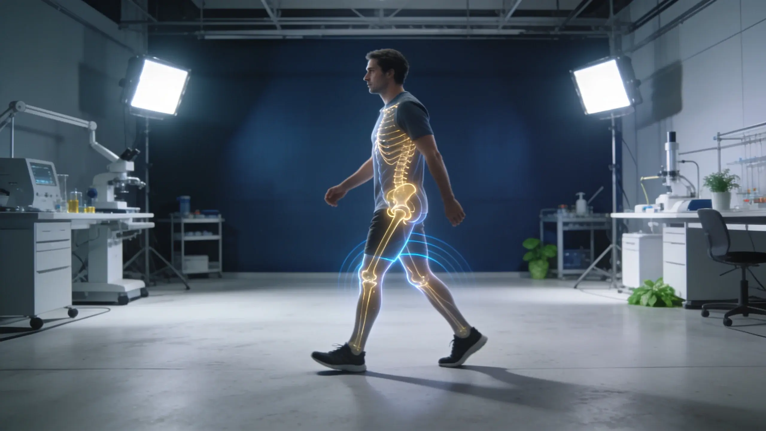
The word joint is often used for three separate objects. The biological joint is the moving relationship between body segments. The exoskeleton joint is a bearing, linkage, sliding guide, compliant mechanism or another connection between device parts. The actuator is the motor, spring or other element that creates or redirects force. Those objects may sit near one another, but they are not interchangeable labels.
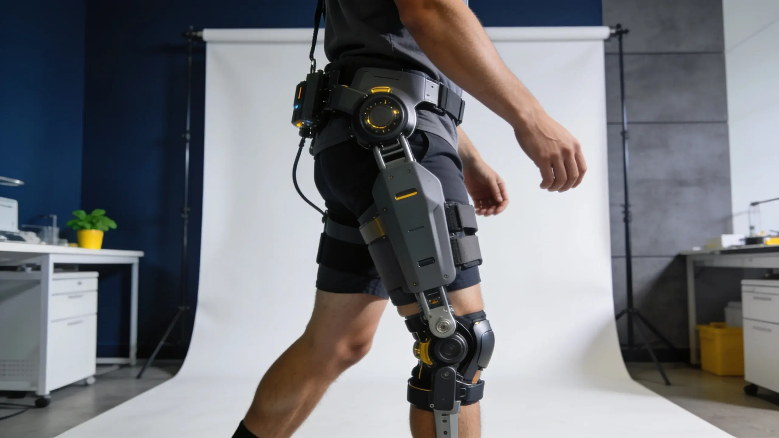
A rigid hip frame, for example, may place a revolute device joint beside the wearer while a motor turns that joint through a transmission. A soft exosuit may span the same body region with textile anchors and a cable, creating a moment without any rigid hinge there. Both architectures can act around the hip, yet only one contains an obvious mechanical joint aligned beside it. The assisted body region therefore does not reveal the device-joint mechanism.
This guide owns that mechanism-level distinction. The exoskeleton-types guide classifies complete systems by power source, structure, body region and intended-use class. The powered-systems guide follows sensing, control and actuation. Here, the question is narrower: which motions does the device permit, which are commanded, which remain passive, and how does the mechanism relate to the moving body?
| Term | What it identifies | What it does not establish |
|---|---|---|
| Biological joint | Relative motion between body segments | The device mechanism placed beside or across it |
| Device joint | Mechanical motion between exoskeleton links or modules | Whether that motion is powered |
| Degree of freedom | One independent coordinate of motion | One motor, one product feature or one body joint |
| Actuated degree of freedom | A coordinate that receives controlled mechanical input | The torque that reaches the wearer |
| Passive degree of freedom | A coordinate allowed without its own commanded actuator | An entirely passive exoskeleton |
| Transmission | The path from an actuator or elastic element to the joint or anchor | The biological moment without a measurement boundary |
A degree of freedom is not a motor count
A degree of freedom, or DoF, is one independent way a mechanism can change configuration. A revolute joint contributes angular motion around an axis. A prismatic joint contributes translation along an axis. A compound mechanism can combine several rotations and translations, while linkage constraints can couple motions so that multiple physical pivots still produce one independent output coordinate.
Active and passive describe how a coordinate is driven, not whether a whole device uses power. An actuated degree of freedom receives commanded input from a motor or another controlled actuator. A passive degree of freedom can rotate or translate in response to body motion, contact loads, springs or the geometry of the coupled system. A powered exoskeleton can therefore include many passive joints around one or two actuated axes.
The reverse counting error also occurs. One actuator can influence more than one joint through a differential, cable network or multi-joint tendon path. A motor and drum can tension a cable that spans a biological joint; a spring can couple two body regions; a linkage can convert one input rotation into a moving center of rotation. Actuator count, device-joint count, independent coordinates and assisted biological joints need separate fields.
Four joint mechanisms appear repeatedly
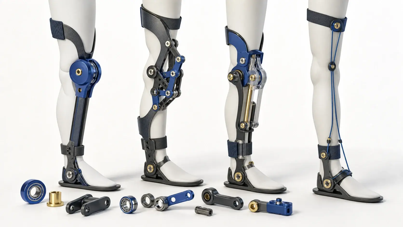
Fixed-axis revolute joints
The simplest device joint resembles a hinge: two links rotate around one defined axis. It is compact, easy to describe and can place a bearing, encoder and transmission at one coordinate. The relevant evidence includes the axis location, allowed range, mechanical stops, bearing arrangement, transmission ratio and the way the adjacent links connect to body interfaces. A drawing of the hinge alone does not show whether its axis remains compatible with body motion.
Polycentric and multi-link joints
A polycentric mechanism uses several pivots and links so that the output motion is not rotation about one permanently fixed point. A four-bar, five-bar or rolling mechanism can make the apparent center move as the linkage changes configuration. The number of visible pivots is not its independent DoF count: linkage constraints may couple those pivots into a single output path.
A 2018 Mechanical Sciences study illustrates the distinction with a compliant five-bar knee mechanism. The authors described two mobility directions in the sagittal plane and no fixed mechanical rotation center for the output. They built a stiffness model and performed force and motion experiments on that specific prototype. The result demonstrates a mechanism family, not a universal alignment rule or a comparison against every fixed-axis joint.
Passive self-aligning chains
A self-aligning chain adds unactuated rotations or translations between the main device frame and an attachment. These coordinates give the coupled human-device system more ways to accommodate axis migration, attachment placement and relative motion. They do not add commanded assistance by themselves. Their travel, stiffness, friction and location determine which mismatches they can absorb.
The 2017 active pelvis-orthosis paper makes the architecture explicit. Its powered hip flexion-extension axis was accompanied by passive degrees of freedom intended to let the device and wearer axes align through movement. Five volunteers walked on a treadmill while the researchers compared body and device kinematics, relative shell movement and discrepancies between the two angle records. That measurement set is more informative than the phrase self-aligning alone.
Hinge-free force paths
Some wearable systems have no rigid joint beside the biological joint they influence. A cable, textile strap or elastic path can pull between anchors on different body segments. The body and wearable interfaces complete the load path, while cable excursion, anchor migration and material stretch replace a rigid-joint angle as important coordinates. Hinge-free does not mean geometry-free; it moves the evidence boundary to routing and attachment behavior.
The wearer and exoskeleton form one coupled chain
Once a rigid exoskeleton attaches at two or more places, the body segments and device links form a closed kinematic chain. Motion must satisfy the constraints of both chains at the same time. A device can line up in one static pose yet accumulate mismatch as the wearer moves because biological axes migrate, attachments shift and simplified mechanical joints follow different paths.
A 2026 Biomimetics study treated compatibility as a configuration-level problem. The researchers built one reconfigurable upper-limb platform that could realize three theoretically compatible families while holding actuation, mass properties, cuffs and sensing arrangement constant. The families differed in how passive joints were distributed between the shoulder and elbow subchains, and interface force and torque were measured at both the upper arm and forearm during two trajectories.
That study also shows why a total DoF figure is incomplete. It compared three four-degree-of-freedom configurations assembled through different modular passive units. Satisfying the same theoretical compatibility conditions did not make the kinematic arrangements mechanically equivalent. A useful record must state where each coordinate sits, whether it rotates or translates, its range, what constrains it and which body-device loop it affects.
The 2020 Wearable Technologies study adds another reporting caution. Its modeled XoTrunk chain had one actuated revolute joint and five passive revolute joints. The authors varied attachment positions and compared device and body workspaces through reachability and capability maps. They explicitly limited the model to kinematics rather than treating it as a force or outcome model. Simulation scope belongs beside every joint claim.
Mechanical freedom and control target are different layers
A controller may estimate or command a variable that is not identical to a device-joint coordinate. In the 2024 Nature study, a clothing-integrated lower-limb exoskeleton estimated biological hip and knee moments and used those estimates to coordinate assistance across both joints during 28 activities. The estimated biological moments were control targets derived from sensor data; they were not simply motor angles renamed as body-joint angles.
The same separation appears at a single joint. A 2022 Nature ankle-exoskeleton study reported regulating torque measured directly at the exoskeleton joint rather than inferring it from motor current. Motor current, transmission output, device-joint torque, interface force and estimated biological moment are five possible measurement boundaries. Their numerical values should not be substituted for one another without a documented model and test.
This is why a specification such as three active DoF remains incomplete. It can describe how many independent coordinates receive commands, but not the controller signal, actuator placement, transmission, measured output, bilateral count or assistance reaching the wearer. Joint architecture and control architecture should be documented in adjacent sections rather than compressed into one number.
How to audit an exoskeleton joint description
- List the assisted biological joint or spanned body regions separately from every device joint.
- For each device coordinate, record revolute, prismatic, compliant or coupled motion and its permitted range.
- Mark each coordinate as actuated, passive, manually adjusted or virtual in a model.
- State whether counts are per side, bilateral totals or shared across both sides.
- Describe the linkage constraint so several physical pivots are not mistaken for several independent DoFs.
- Name the actuator and transmission separately from the joint they influence.
- Identify the measurement boundary: motor, transmission, device joint, interface or estimated biological joint.
- Record attachment placement, relative movement and the task used to evaluate the coupled chain.
- Separate simulation, bench, mannequin and human testing rather than merging their conclusions.
- Treat missing range, friction, stiffness or interface data as not verified.
What joint counts cannot tell you
More degrees of freedom are not automatically better. Additional passive motion can accommodate more configurations, but it also changes size, mass, friction, stiffness and the routes through which forces travel. Fewer coordinates can create a simpler mechanism, yet only if the resulting path remains compatible with the defined movement. The correct count is architecture- and task-specific, not a leaderboard.
A joint diagram also cannot establish whole-system performance or suitability. It does not show control timing, interface behavior under load, battery behavior, environmental limits or the evidence for a particular intended use. Use joint mechanics to understand how motion is constrained and transmitted, then move to controller, body-region and exact-system evidence for the next question.
Sources
- Biomimetics: upper-limb joint-configuration comparison (2026)
- Journal of NeuroEngineering and Rehabilitation: pelvis-orthosis joint interaction (2017)
- Wearable Technologies: exoskeleton kinematic-design robustness (2020)
- Mechanical Sciences: compliant five-bar knee-joint mechanism (2018)
- Nature: biological hip-and-knee moment estimation (2024)
- Nature: portable rigid-frame ankle exoskeleton (2022)
Continue your research
Key facts
- A biological joint, a device joint and an actuator are three different things.
- One degree of freedom describes one independent motion, not automatically one motor or one assisted direction.
- Active degrees of freedom receive commanded input; passive degrees move through loads, geometry, springs or the wearer.
- Polycentric linkages and self-aligning chains can follow motion without one fixed device axis.
- A hinge-free cable or textile path can create a moment around a biological joint without a rigid joint beside it.
Frequently asked questions
What is a degree of freedom in an exoskeleton?
It is one independent coordinate of mechanism motion, such as rotation around an axis or translation along a guide. Several physical pivots can be constrained into one degree of freedom, and one powered device can include both actuated and passive degrees.
Does every exoskeleton joint need a motor?
No. Some joints are passive and move because of body motion, contact loads, springs or linkage geometry. A motor may also sit away from the joint and transmit force through a cable, belt, gearbox or linkage.
What is the difference between active and passive degrees of freedom?
An active degree receives commanded mechanical input from an actuator. A passive degree has no independently commanded actuator and instead accommodates motion through its geometry, loads or elastic elements. A powered exoskeleton can contain both.
Can an exoskeleton assist a joint without a mechanical hinge?
Yes. A cable, textile or elastic path can span a biological joint and create a moment between anchors on adjacent body segments. The evidence then shifts from hinge alignment to anchor location, routing, material deformation and measured force transfer.