Knee Exoskeletons: How Knee Assistance Systems Work
A research-led guide to knee flexion and extension assistance, joint alignment, wearable interfaces, control strategies and evidence limits.

Research standard: this guide draws on primary records, technical documentation and documented field experience. Volatile facts such as price, availability and firmware are reviewed on a dated schedule.
What counts as a knee exoskeleton
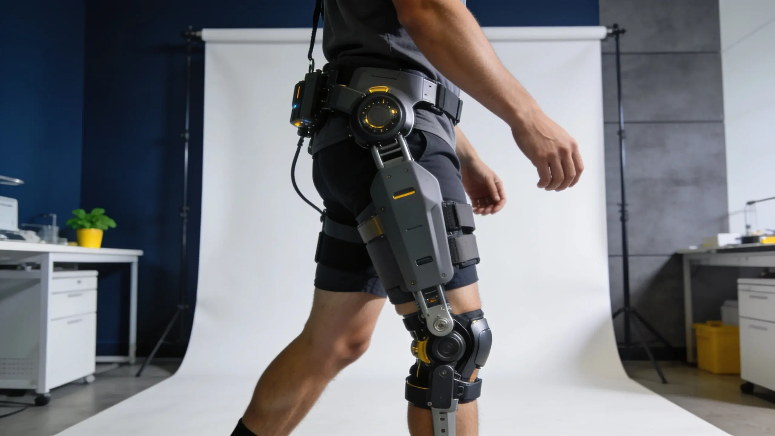
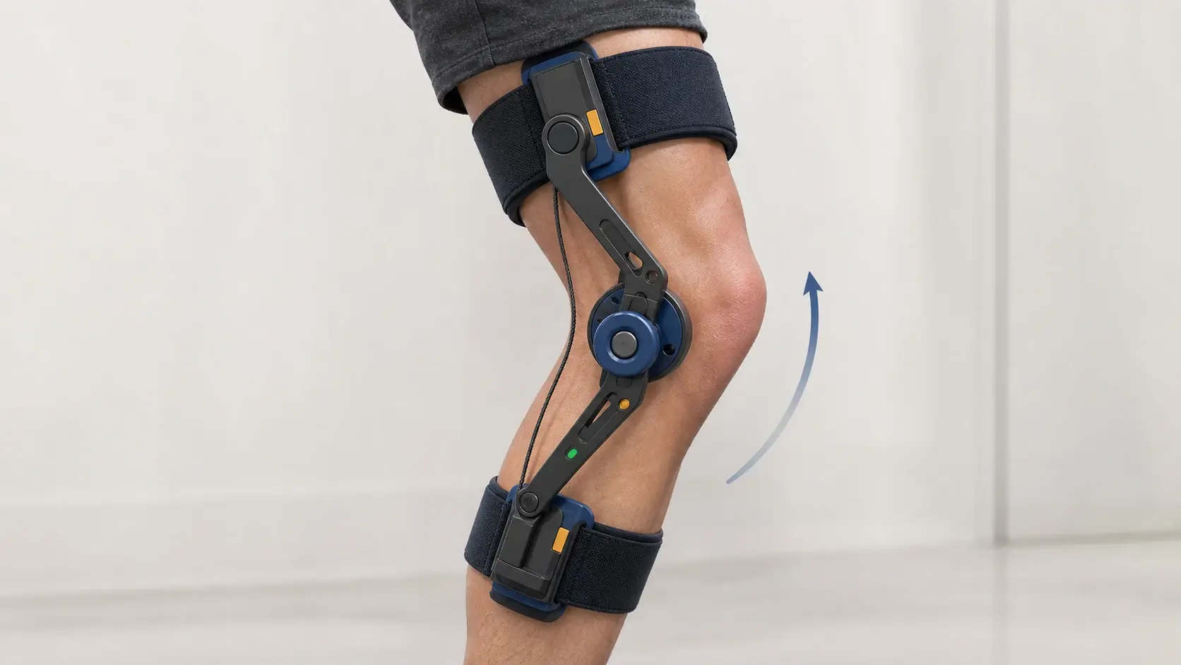
Knee exoskeleton is a joint-location description, not one device category. It covers wearable systems that create, store or redirect a moment around the knee through contact points above and below the joint. A rigid system may place an actuator and mechanical linkage beside the leg. A soft knee exosuit may tension a cable across the knee between textile anchors. A passive design can use springs, dampers or other mechanical elements without a powered actuator.
That scope is deliberately narrower than the general exoskeleton-types guide and deeper than the knee-assist glossary entry. The glossary defines the term; this guide explains the architecture and evidence needed to interpret it. It does not evaluate a current product, recommend a use or establish a medical, workplace or consumer outcome.
The comparison starts with five fields: the direction of assistance, the movement phase, the force path, the joint or anchor geometry and the controller. Names such as powered knee exoskeleton, knee brace, knee robot and knee exosuit overlap across research papers. Describing the mechanism is more reliable than inferring performance from the label.
Knee flexion and extension are different targets
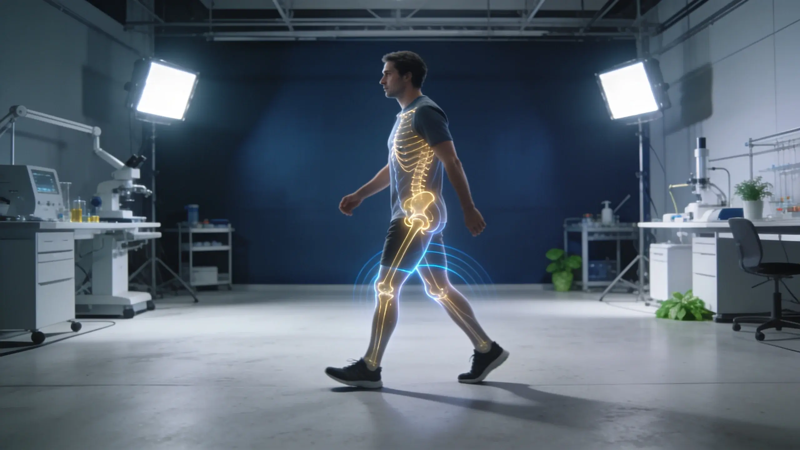
Knee extension straightens the leg; knee flexion bends it. Both occur repeatedly during walking, but the knee's role changes across stance and swing. Early stance includes flexion as the limb accepts the body's movement, followed by extension as the body advances. During swing, flexion helps shorten the leg and extension prepares it for the next contact. Stairs, slopes, squats and transitions create different angle, speed and torque patterns from level walking.
| Assistance target | Mechanical action | What the label does not establish |
|---|---|---|
| Extension assistance | Creates a moment that tends to straighten the knee | Which phase, task or wearer the profile matches |
| Flexion assistance | Creates a moment that tends to bend the knee | That the same timing works in stance and swing |
| Resistive or damping action | Opposes motion and may absorb mechanical energy | That resistance is useful throughout the movement |
| Passive energy return | Stores energy in an elastic element and releases it later | That one stiffness and preload match every speed or activity |
A headline torque number omits most of this pattern. Direction, onset, rise time, peak, duration and offset all influence the interaction. A controller can request the same peak moment at two different phases and create two different mechanical effects. A passive element is also time-dependent, but its timing emerges from geometry, stiffness, preload and the wearer's movement rather than a software command.
Why knee alignment is a design problem
A simple door hinge rotates about one fixed axis. The human knee combines rotation with translation as the femur and tibia move relative to each other, and the apparent center of rotation shifts with knee angle. A rigid exoskeleton joint placed beside the leg therefore cannot be judged only by whether two axes line up in one static pose. Link geometry, attachment movement and the allowed passive degrees of freedom determine how the alignment changes through motion.
A 2022 self-aligning research prototype used rolling gears intended to approximate the relative motion of the femur and tibia. Its authors evaluated the joint on a bench and then tested torque tracking with three participants walking on a treadmill. The bench measurement reported an average separation of 2.52 ± 1.62 millimetres between the prototype's center of rotation and the reference knee trajectory from 0 to 100 degrees. That is a result for one mechanism and test method, not an acceptable limit for all devices.
The study also illustrates why simulation, benchtop and human tests should remain separate. Simulated improvement against a fixed-axis design can answer a geometry question. A bench rig can measure the device joint under controlled motion. Human walking adds soft-tissue movement, strap compliance and individual anatomy. None of those layers alone proves how an unrelated commercial system will interact with a particular wearer.
Rigid, soft and hybrid force paths
| Architecture | Typical load path | Primary evidence question |
|---|---|---|
| Rigid powered frame | Actuator, device joint and links connect thigh and shank interfaces | How geometry, passive freedoms and attachments manage relative motion |
| Cable-driven rigid frame | An off-axis motor pulls a cable that rotates a linked device joint | How cable compliance, transmission and friction affect delivered torque |
| Soft knee exosuit | A cable or tendon pulls between textile anchors across the knee | How anchor deformation and migration change the effective moment arm |
| Passive or quasi-passive system | Springs, clutches or dampers connect body interfaces without continuous motor power | Which movement phases engage, store, resist or release energy |
| Hybrid structure | Rigid anchor pieces and compliant transmission share the load | Which part sets alignment and which part accommodates movement |
Rigid and soft are not synonyms for powerful and gentle. A rigid structure can include compliant joints and distributed interfaces. A textile system can still concentrate load where a cable terminates or an anchor resists shear. In every architecture, forces must close through at least two body contacts. Their spacing creates the external moment around the knee, while deformation and migration can change the effective lever arm.
The 2021 hinge-free knee exosuit study makes that distinction visible. Its Bowden cable crossed in front of the knee and pulled between semi-rigid thigh and calf wraps, with no rigid structure spanning the joint. The paper reported 1.14 kilograms worn for a unilateral setup and 1.72 kilograms for the bilateral arrangement, while the actuation remained tethered off the body. The mass figures describe the worn components, not a self-contained portable product.
That study evaluated six healthy participants on a treadmill at a ten-degree incline and decline. The authors varied assistance profiles to study knee mechanics and compared the unpowered suit with a no-suit condition before interpreting active assistance. The useful general lesson is methodological: report the anchor design, tethering, participants, slope, profile and baseline together. The numerical outcome cannot be transferred to a rigid product or to level overground walking.
From sensor data to knee torque
A powered knee system needs to decide what movement is occurring, whether assistance is requested and what moment to command. Sensors may measure device-joint angle, segment orientation, angular velocity, foot contact, cable force, motor current or interface load. A state estimator converts those signals into a movement phase or continuous state. A higher-level profile chooses the desired assistance, and a lower-level controller attempts to make the actuator follow it.
| Control layer | Question to record | Interpretation limit |
|---|---|---|
| Sensing | Which body, interface or device signals are measured? | A device encoder does not necessarily equal biological knee angle |
| State estimation | Is movement divided into phases or represented continuously? | A model validated at fixed speeds may not cover transitions |
| Assistance profile | How are direction, magnitude and timing selected? | A study-tuned profile may differ from a default mode |
| Torque control | Where is actual torque measured or estimated? | Motor output is not automatically the moment reaching the body |
| Fallback state | What does the research condition call unpowered, free or zero torque? | These baselines can have different residual resistance |
A 2022 quasi-direct-drive prototype used a continuous stiffness-based controller rather than switching only between discrete assistance phases. The paper reported a 14-newton-metre assistance capability, a 16-hertz stiffness-control bandwidth under its stated test condition and 0.34-newton-metre root-mean-square torque-tracking error across the tested stiffness range. It also evaluated knee-moment estimation at three walking speeds and during transitions.
Those values characterize the tested prototype and controller, not knee exoskeletons as a class. Bandwidth depends on the defined input and loading condition. Tracking error depends on the command, sensors and calculation method. The most useful comparison keeps desired torque, measured device torque, estimated biological moment and interface force in separate fields.
Controllers can use the movement and the environment
Knee control does not have to depend on a single repeated gait cycle. A 2025 npj Robotics paper combined right and left knee angles and angular velocities, trunk motion and first-person camera features to predict when a carbon-frame knee robot should switch between active and free states. Its experimental sequence mixed walking, squatting and stepping up rather than repeating only steady level walking.
The study involved two healthy male participants. One participant supplied the labeled data used to train the model, and the second tested whether the learned strategy generalized beyond that person. Each assisted evaluation lasted three minutes and included 30 squats plus 15 step-ups with each leg. This is a compact research demonstration, not evidence of broad population performance or readiness for an uncontrolled environment.
Its value for a general architecture guide is the separation between recognizing a context and delivering torque. The vision-and-kinematics model generated an active-or-free command; pneumatic artificial muscles produced the knee-joint moment. A complete record must describe both layers. High classification accuracy would not by itself establish accurate force delivery, and accurate torque tracking would not by itself show that assistance was requested at the right moment.
How to interpret a knee-exoskeleton study
- Identify the exact prototype, assisted side or sides, and whether the system is tethered or portable.
- Record extension, flexion, resistance or energy-return direction and the movement phase targeted.
- Describe rigid links, passive degrees of freedom, cables, textiles, cuffs and other body interfaces.
- Separate static alignment, simulated alignment, benchtop motion and human-use observations.
- Distinguish commanded actuator output, device-joint torque, interface load and estimated biological moment.
- Preserve the participants, activity, speed or slope, duration, familiarization and assistance profile.
- Keep no-device, unpowered, free, zero-torque and alternative-device baselines distinct.
- Do not apply a research prototype result to an exact commercial model without model-specific evidence.
ASTM F3528-21 reinforces the importance of task definition from another angle. Its gait test method standardizes a straight-path setup, procedure and recording for generic gait capability, while noting that other movements and terrain complexities require other test methods. The standard does not make every gait result interchangeable; it provides a repeatable context for the specified test.
This is why two well-run knee studies can answer different questions. One may isolate joint geometry on a bench. Another may tune a tethered exosuit on a slope. A third may test a portable controller across speed transitions. The correct synthesis is not an average score. It is a map of which mechanism, activity, baseline and outcome each experiment actually measured.
Knee assistance versus hip assistance
Hip and knee systems should not share one undifferentiated comparison row. A hip device commonly reacts between a waist or pelvis interface and the thigh. A knee device usually closes its load path between thigh and shank interfaces and must account for the knee's changing geometry. The joints also contribute differently across walking, slopes, stairs and transitions, so matching a peak torque number does not make the mechanisms equivalent.
A multi-joint device adds another layer: assistance at one joint can change the movement and demand observed at another. Record each actuated and passive joint, its direction, controller and test condition separately. Use the joint label as a research filter, then compare exact architectures within the same intended-use class. Product suitability and current market claims require their own exact-model review.
Sources
- ASTM F3528-21: Standard Test Method for Exoskeleton Use — Gait
- IEEE Robotics and Automation Letters: hinge-free knee-extension exosuit (2021)
- Frontiers in Human Neuroscience: self-aligning cable-driven knee exoskeleton (2022)
- IEEE Open Journal of Engineering in Medicine and Biology: continuous knee-torque control (2022)
- npj Robotics: vision-and-kinematics knee-assistance control (2025)
Continue your research
Key facts
- Knee assistance can target extension, flexion, energy absorption or energy return at different movement phases.
- The biological knee does not behave like one fixed hinge through its full range of motion.
- Rigid frames, cable-driven systems, textile exosuits and passive mechanisms create different load paths.
- Actuator torque, torque measured at a device joint and the moment reaching the wearer are not interchangeable values.
- Prototype results remain specific to the hardware, participants, task, controller and comparison condition tested.
Frequently asked questions
What does a knee exoskeleton do?
It creates, stores, redirects or resists a moment around the knee through body contacts above and below the joint. The exact effect depends on direction, timing, architecture, interface and movement.
Is a knee exosuit the same as a knee exoskeleton?
The terms overlap, but exosuit usually signals a textile or cable-based load path without a rigid joint spanning the knee. Describe the actual links, anchors and transmission because research naming is not consistent.
Why is knee-joint alignment difficult?
The biological knee combines rotation and translation, so its apparent center of rotation changes with angle. A device must manage that changing geometry through linkage design, passive motion, compliant interfaces or a hinge-free force path.
Does more knee torque mean better assistance?
No. Torque direction, timing, duration, tracking, interface deformation, residual resistance and the movement being tested all affect interpretation. A peak value alone cannot establish a whole-system result.